



Hino P20B4 Fault Code: Coolant cut off valve – circuit (circuit high)





TECHNICAL DESCRIPTION
DCU detects malfunctions based on the coolant cut off valve circuit voltage.
DESCRIPTION OF MALFUNCTION
Malfunction of coolant cut off valve is detected.
DTC SET CONDITION
DTC Detection Condition:
− Starter switch ON. − Coolant cut off valve duty > 0%
Judgment Criteria:
Coolant cut off valve voltage = 2.7 V for 0.1 sec.
RESET CONDITION
After having restored to the normal conditions.
INDICATION, WARNING OR SYSTEM CONTROL REGULATION WHEN THE DTC IS SET
MIL: ON
SYMPTOMS ON THE VEHICLE WHEN THE DTC IS SET
Symptoms on the Vehicle Due to Malfunction: Control will not work properly if the DEF freezes.
PRE-INSPECTION WORK
Check if the battery voltage is in the normal range.
AFTER-INSPECTION WORK
− Clear all past DTCs. − Check if no DTC is stored after test drive.
POSSIBLE CAUSES
− Harness disconnection or short-circuit − Looseness or unsteady contact of connector − Coolant cut off valve malfunction.
INSPECTION PROCEDURE
TROUBLESHOOTING STEPS
Step 1) Inspect the coolant cut off valve connector.
Check the connection of the coolant cut off valve connector (Looseness and poor contact). Was any failure found?
| Yes – Connect securely, repair if needed. Clear all past DTCs. Check if no DTC is stored after test drive. | No – Go to Step 2. |
Step 2) Check the coolant cut off valve unit.
- Set the starter switch to the “LOCK” position.
- Remove the connector of the coolant cut off valve.
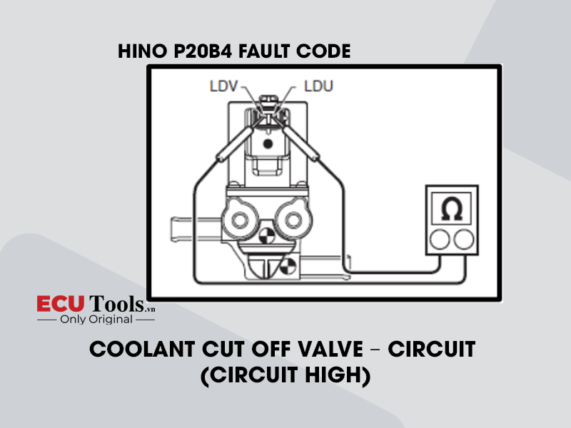
- Use the electrical tester to measure the resistance between the terminals of the coolant cut off valve.
| MEASUREMENT CONDITIONS | TESTER CONNECTIONS | STANDARD VALUES |
| Starter switch: LOCK | Coolant cut off valve connector LDU – LDV | 20°C {68°F}: 9.04 – 9.52 Ω |
 Do the measurements meet the standard value?
| Yes – Go to Step 3. | No – Replace the coolant cut off valve. Clear all past DTCs. Check if no DTC is stored after test drive. |
Step 3) Check for short-circuit in the coolant cut off valve wire harness.
- Disconnect the DCU 86P connector.
- Connect the signal check harness and use the electrical tester to measure the resistance between the terminals of the DCU 86P vehicle-side connector and the ground.
| MEASUREMENT CONDITIONS | TESTER CONNECTIONS | STANDARD VALUES |
| Starter switch: LOCK | DCU 86P vehicle-side connector WMV+ – Ground WMV- – Ground | ∞ Ω |
 Do the measurements meet the standard value?
| Yes – Go to Step 4. | No – Repair or replace the harness. Clear all past DTCs. Check if no DTC is stored after test drive. |
Step 4) Check for disconnection in the coolant cut off valve wire harness.
- Connect the coolant cut off valve connector.
- Connect the signal check harness and use the electrical tester to measure the resistance between the terminals of the DCU 86P vehicle-side connector.
| MEASUREMENT CONDITIONS | TESTER CONNECTIONS | STANDARD VALUES |
| Starter switch: LOCK | DCU 86P vehicle-side connector WMV+ – WMV- | 20°C {68°F}: 9.04 – 9.52 Ω |
 Do the measurements meet the standard value?
| Yes – Go to Step 5. | No – Repair or replace the harness. Clear all past DTCs. Check if no DTC is stored after test drive. |
Step 5) Check the DTC detected (DCU).
- Connect the vehicle to the diagnostic tool.
- Set the starter switch to the “ON” position.
- Select [DCU] and check if P20B4 has been detected.
Has DTC P20B4 been detected?
| Yes – Replace the DCU. (After replacing the DCU, perform a DPR forced regeneration.) Clear all past DTCs. Check if no DTC is stored after test drive. | No – Procedure completed. Clear all past DTCs. Check if no DTC is stored after test drive. |
Whatsapp: +84.899.402.402
Facebook: ECUTools.vn
Youtube: ECUToolsvn
Tiktok: ECUTools
Website: ECUTools.vn
RELATED NEWS
See all