



Hino P0104 Fault Code: Air Flow Sensor – Out Of Range




Technical description
The air flow sensor installed to the air cleaner consistently measures an intake air volume
Description of malfunction
The air flow sensor value cannot be correctly recognized
Dtc set condition
Check Conditions:
- Starter switch ON
- Battery voltage is in the range of 10V to 16V
- Engine speed is at least 725 r/min
- The conditions described above remain for 5 seconds or longer
Judgment Criteria:
Output of the air flow sensor remains less than 2.0 kHz (3.9 kg/h) for 3 seconds or longer
Reset condition
After normal operation is restored and the starter switch is turned to LOCK
Indication, warning or system control
Regulation when the dtc is set
- MIL: ON
- SVS light: OFF
- Engine output is restricted
Symptoms on the vehicle when the dtc is set
Symptoms on the vehicle due to backup control (fail safe function):
Engine output is insufficient
Pre-inspection work
Check that the battery voltage is in the normal range.
After-inspection work
- Clear all past DTCs
- Check that no DTC is stored after test drive
Possible causes
- Sensor disconnected from the measured part or sensing unit malfunctioning (due to dirt, clogging, damage, etc.)
- Engine ECU sensor power supply (air flow sensor dedicated 12 V power supply) malfunction or internal circuit malfunction
- Sensor harness disconnection, short-circuit
- Poor connector contact or faulty connector fit
- Sensor harness high frequency noise
Inspection procedure
Troubleshooting steps
Step 1: Check the DTC detected (Engine ECU) 1 [Diagnostic Tool]
- Set the starter switch to the “LOCK” position.
- Connect the vehicle to the diagnostic tool.
- Set the starter switch to the “ON” position.
- Select [Engine] and check if any DTC other than P0104 (for example, P0642, P0643, P0652, P0653) has been detected.
NOTE: Due to sensor power supply failures, P0104 may have been detected. First perform the diagnostic related to the sensor power supply
Has a DTC other than P0104 been detected?
| Yes | Go to the diagnostic procedure of a related DTC |
| No | Go to Step 2 |
Step 2: Inspect the air flow sensor connector
Check the connection of the air flow sensor connector (Looseness and poor contact)
Were any failures found?
| Yes | Connect securely, repair if needed. Clear all past DTCs. Check that no DTC is detected
after test drive |
| No | Go to Step 3 |
Step 3: Inspect the air flow sensor.
- Check the installation of the air flow sensor
- Make sure there is no dirt or damage to the air flow sensor
Were any failures found?
| Yes | If dirt, clogging or damage was found in sensing unit, replace the air flow sensor. Clear all past DTCs. Check that no DTC is detected after test drive |
| No | Go to Step 4 |
Step 4: Inspect for short-circuit of the air flow sensor harness
- Set the starter switch to the “LOCK” position.
- Connect the signal check harness to the engine ECU vehicle-side harness. (Do not connect the harness to the ECU)
- Disconnect the air flow sensor connector
- Use the electrical tester to measure the resistance between the terminals of the engine ECU (signal check harness) and ground
| MEASUREMENT CONDITIONS | TESTER CONNECTIONS | STANDARD VALUES |
| Starter switch: LOCK | Engine ECU (signal check
harness) AFSI(E74) – Ground AG4(E78) – Ground AFVB(E12) – Ground |
∞ Ω |

Do the measurements meet the standard value?
| Yes | Go to Step 5 |
| No | Repair or replace the harness. Clear all past DTCs. Check that no DTC is detected after test drive. |
Step 5: Inspect disconnection of the air flow sensor harness
Use the electrical tester to measure the resistance between the terminals of the engine ECU (signal check harness) and air flow sensor vehicle-side connector
| MEASUREMENT CONDITIONS | TESTER CONNECTIONS | STANDARD VALUES |
| Starter switch: LOCK | Engine ECU (signal check
harness) – Air flow sensor vehicle-side connector AFSI(E74) – AFSG AG4(E78) – AFGD AFVB(E12) – AFVB |
1 Ω or less |

Do the measurements meet the standard value?
| Yes | Go to Step 6 |
| No | Repair or replace the harness. Clear all past DTCs. Check that no DTC is detected after test drive. |
Step 6: Inspect the air flow sensor power supply
- Connect the signal check harness to the engine ECU
- Set the starter switch to the “ON” position
- Use the electrical tester to measure the voltage between the terminals of the air flow sensor vehicleside connector
| MEASUREMENT CONDITIONS | TESTER CONNECTIONS | STANDARD VALUES |
| Starter switch: ON | Air flow sensor vehicle-side connector
AFVB – AFGD |
4.5 – 5.5 V |

Do the measurements meet the standard value?
| Yes | Go to Step 7 |
| No | Replace the engine ECU. Clear all past DTCs. Check that no DTC is detected after test drive. |
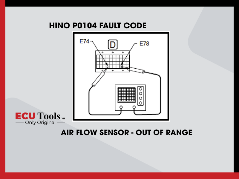
Step 7: Inspect the air flow sensor signal
- Set the starter switch to the “LOCK” position
- Connect the air flow sensor connector
- Start the engine
- Use the oscilloscope to measure the signal voltage between the terminals in the engine ECU (signal check harness)
| MEASUREMENT CONDITIONS | TESTER CONNECTIONS | STANDARD VALUES |
| After engine warm-up,
with engine idling |
Engine ECU (signal check harness)
AFSI(E74) – AG4(E78) |
5 – 6 kHz |

Do the measurements meet the standard value?
| Yes | Go to Step 8 |
| No | Replace the air flow sensor. Clear all past DTCs. Check that no DTC is detected after test drive. |
Step 8: Check the DTC detected (Engine ECU) 2 [Diagnostic Tool]
- Perform engine warm-up. (Engine coolant temperature: 60°C {140°F} or more)
- Stop the engine and set the starter switch to the “ON” position
- Select [Engine] and check if P0104 has been detected
Has DTC P0104 been detected?
| Yes | Replace the engine ECU. Clear all past DTCs. Check that no DTC is detected after test drive. |
| No | Procedure complete. Clear all past DTCs. Check that no DTC is detected after test drive. |
Whatsapp: +84.899.402.402
Facebook: ECUTools.vn
Youtube: ECUToolsvn
Tiktok: ECUTools
Website: ECUTools.vn
RELATED NEWS
See all