



Hino P226C Fault Code: Boost Pressure Slow Response




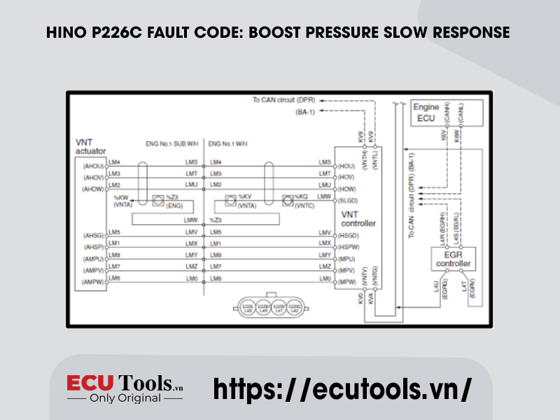
Technical Description
− The VNT actuator stepless moves the nozzle vane via the REA (Rotary Electric Actuator) and controls turbocharger speed and boost pressure.
− The sensor inside the REA detects the amount of actuator movement and constantly monitors the nozzle vane target opening and actual opening.
Description Of Malfunction
VNT response delay is detected.
Dtc Set Condition
DTC Detection Condition:
10 minutes after engine start-up:
− Estimated boost pressure variation, which is calculated from the engine speed and fuel injection rate, is either ≥ 30 kPa/sec {4.4 psi} or ≤ -35 kPa/sec {-5.1 psi}.
− Engine speed fluctuation is less than 100 r/min.
Judgment Criteria:
Difference between [estimated boost pressure – actual boost pressure] is either ≥ 55 kPa {8.0 psi} or ≤ -30 – -60 kPa {-4.4 – -8.7 psi}.
Reset Condition
After normal operation is restored and the starter switch is on the “LOCK” position.
Indication, Warning Or System Control Regulation When The Dtc Is Set
− MIL: ON
− SVS light: OFF
Symptoms On The Vehicle When The Dtc Is Set
Symptoms on the vehicle due to malfunction:
Faulty engine revving (engine hesitation).
Pre-Inspection Work
Check that the battery voltage is in the normal range.
After-Inspection Work
− Clear all past DTCs.
− Check that no DTC is detected after test drive.
Possible Causes
− Hesitation or sticking due to corrosion of VNT link system rods.
− Faulty connector contact to REA.
− Harness disconnection or short-circuit.
− EGR valve malfunction.
− Intake system failure.
− Boost pressure sensor malfunction.
Inspection Procedure
Troubleshooting Steps
Step 1) Check the response delay of the VNT controller [Diagnostic Tool].
- Set the starter switch to the “LOCK” position.
- Connect the vehicle to the diagnostic tool.
- Set the starter switch to the “ON” position.
- Select [Engine] on the screen of the diagnostic tool. Select [VNT inspection] from the [Inspection Menu] and inspect the response delay at the Target VNT position and Actual VNT position.
CAUTION: Perform the inspection while the engine is stopped to avoid engine damages.
Inspection Procedure:
- Select [Inspection Menu].
- Select [VNT inspection].
- Click [Start inspection].
- Click [VNT UP].
− Inspect the response delay at each step of the Target VNT position and Actual VNT position from 0 to 90%.
- Click [VNT DOWN].
− Inspect the response delay at each step of the Target VNT position and Actual VNT position from 90 to 0%.
NOTE: The VNT opening position changes of 10% per step between 0 – 90%.
| STANDARD VALUES |
| The response delay should be less than 3 seconds. |
Do the measurements meet the standard value?
| Yes – Go to Step 2. | No – Replace the turbocharger. Clear all past DTCs. Check that no DTC is detected after test drive. |
Step 2) Check the response delay of the EGR valve [Diagnostic Tool].
Check the time lag (following characteristics) of the target EGR valve opening and actual EGR valve opening.
CAUTION: Perform the inspection while the engine is stopped to avoid engine damages.
Inspection Procedure:
- Select [Inspection Menu].
- Select [EGR inspection].
- Click [Start inspection].
- Click [EGR opening UP]:
− Check each step from 0% – 100% of the time lag (following characteristics) of the target EGR valve opening and actual EGR valve opening.
- Click [EGR opening DOWN]:
− Check each step from 100% – 0% of the time lag (following characteristics) of the target EGR valve opening and actual EGR valve opening.
NOTE: In EGR openings from 0% – 100%, 1 step corresponds to a 10% change.
| STANDARD VALUES |
| The response delay should be less than 5 seconds. |
Do the measurements meet the standard value?
| Yes – Go to Step 3. | No – Replace the EGR valve. Clear all past DTCs. Check that no DTC is detected after test drive. |
Step 3) Inspect the air cleaner element.
- Check there is no dirt, damage or clogging in the air cleaner element.
- Make sure the element is an OEM genuine part.
Were any failures found?
| Yes – Clean or replace the air cleaner element. Clear all past DTCs. Check that no DTC is detected after test drive. | No – Go to Step 4. |
Step 4) Check the air intake system.
Check the air intake system (between air flow sensor and diesel throttle) for dirt, clogging, or damage.
Were any failures found?
| Yes – Clean or replace the faulty part. Clear all past DTCs. Check that no DTC is detected after test drive. | No – Go to Step 5. |
Step 5) Inspect the boost pressure sensor.
- Check the installation of the boost pressure sensor.
- Make sure there is no dirt or damage to the boost pressure sensor.
Were any failures found?
| Yes – Clean the boost pressure sensor and install it properly. If dirt, clogging or damage was found, replace the sensor. Clear all past DTCs. Check that no DTC is detected after test drive. | No – Go to Step 6. |
Step 6) Check the connector connection [Diagnostic Tool].
- Set the starter switch to the “LOCK” position.
- Disconnect the connector connecting the VNT actuator and VNT controller and then securely reconnect it.
- Set the starter switch to the “ON” position.
- Select [Engine] and check if P226C has been detected.

Has DTC P226C been detected?
| Yes – Go to Step 7. | No – Procedure completed. (Poor contact of the connector) Clear all past DTCs. Check that no DTC is detected after test drive. |
Step 7) Check the VNT controller power supply circuit.
- Set the starter switch to the “LOCK” position.
- Disconnect the VNT controller connector.
- Set the starter switch to the “ON” position.
- Use the electrical tester to measure the resistance from the VNT controller vehicle-side connector to each of the terminals in the VNT actuator vehicle-side connector.
| MEASUREMENT CONDITIONS | TESTER CONNECTIONS | STANDARD VALUES |
| Starter switch: ON | VNT controller vehicle-side connector VNTV – VNTG | 10 V or more |

Do the measurements meet the standard value?
| Yes – Go to Step 8. | No – Check the VNT controller power supply circuit. Clear all past DTCs. Check that no DTC is detected after test drive. |
Step 8) Inspect the VNT actuator harness.
- Set the starter switch to the “LOCK” position.
- Disconnect the connector connecting the VNT actuator and VNT controller
- Use the electrical tester to measure the resistance from the VNT controller vehicle-side connector to each of the terminals in the VNT actuator vehicle-side connector.
| MEASUREMENT CONDITIONS | TESTER CONNECTIONS | STANDARD VALUES |
| Starter switch: LOCK | Controller – Actuator
1 terminal – 4 terminal 2 terminal – 3 terminal 3 terminal – 2 terminal 4 terminal – 5 terminal 8 terminal – 1 terminal 10 terminal – 8 terminal 11 terminal – 7 terminal 12 terminal – 6 terminal |
1 Ω or less |

Do the measurements meet the standard value?
| Yes – Go to Step 9. | No – Repair or replace the harness. Clear all past DTCs. Check that no DTC is detected after test drive. |
Step 9) Check the operation of the VNT actuator (DC motor) [Diagnostic Tool].
- Connect the VNT controller and VNT actuator connector.
- Set the starter switch to the “ON” position.
- Erase the trouble history.
- Set the starter switch to the “LOCK” position.
- Set the starter switch to the “ON” position again.
- Select [Engine] and check if P226C has been detected. NOTE: Turn the starter switch OFF and ON verifies the wiping operation of the VNT actuator (DC motor).
Has DTC P226C been detected?
| Yes – Replace the turbocharger. Clear all past DTCs. Check that no DTC is detected after test drive. | No – Procedure completed. Clear all past DTCs. Check that no DTC is detected after test drive. |
Whatsapp: +84.899.402.402
Facebook: ECUTools.vn
Youtube: ECUToolsvn
Tiktok: ECUTools
Website: ECUTools.vn
RELATED NEWS
See all