



Hino P21C4 Fault Code: DEF heater relay failure (high)




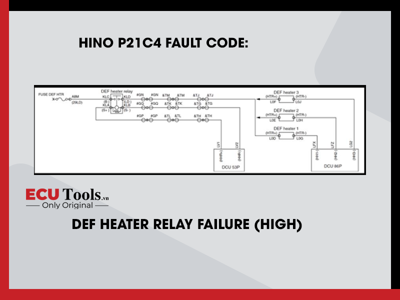
TECHNICAL DESCRIPTION
− Electrify the DEF heater relay to prevent the freezing of DEF pipings. − DCU detects +B short-circuit based on the DEF heater circuit voltage.
DTC SET CONDITION
DTC Detection Condition:
Starter switch ON.
Judgment Criteria:
DEF heater relay circuit voltage is less than 2.7 V.
RESET CONDITION
After having restored to the normal conditions.
INDICATION, WARNING OR SYSTEM CONTROL REGULATION WHEN THE DTC IS SET
− MIL: ON − SCR malfunction light: ON.
SYMPTOMS ON THE VEHICLE WHEN THE DTC IS SET
Symptoms on the Vehicle Due to Malfunction Deterioration of the function to prevent the freezing of DEF pipings.
PRE-INSPECTION WORK
Check that the battery voltage is in the normal range.
AFTER-INSPECTION WORK
− Clear all past DTCs. (Also, clear DTC P204F (DEF SCR system failure) of the engine ECU side.) − Check if no DTC is stored after test drive.
POSSIBLE CAUSES
− Harness short-circuit − DEF heater relay malfunction.
INSPECTION PROCEDURE
TROUBLESHOOTING STEPS
Step 1) Inspect the DEF heater relay. Check the connection of the DEF heater relay (inside cab) (Looseness or poor contact). Was any failure found ?
| Yes – Connect securely, repair if needed. Clear all past DTCs. (Also, clear DTC P204F (DEF SCR system failure) of the engine ECU side.) Check if no DTC is stored after test drive. | No – Go to Step 2. |
Step 2) Inspect the DEF heater relay unit.
- Set the starter switch to the “LOCK” position.
- Disconnect the DEF heater relay.
- Use the electrical tester to measure the resistance between the terminals of the DEF heater relay.
| TESTER CONNECTIONS | STANDARD VALUES |
| DEF heater relay terminals | 1 in the figure: 320 Ω 2 in the figure: ∞ Ω |

Do the measurements meet the standard value ?
| Yes – Go to Step 3. | No – Replace the DEF heater relay. Clear all past DTCs. (Also, clear DTC P204F (DEF SCR system failure) of the engine ECU side.) Check if no DTC is stored after test drive. |
Step 3) Inspect the DEF heater relay power supply circuit.
- Set the starter switch to the “ON” position.
- Use the electrical tester to measure the voltage between each terminal in the DEF heater relay vehicle-side connector (inside the cab) and ground.
| MEASUREMENT CONDITIONS | TESTER CONNECTIONS | STANDARD VALUES |
| Starter switch: ON Disconnect DEF heater relay | DEF heater relay vehicle-side connector B – Ground S+ – Ground | 10 V or more |
 Do the measurements meet the standard value ?
| Yes – Go to Step 4.. | No – Repair or replace the DEF heater relay power supply circuit. Clear all past DTCs. (Also, clear DTC P204F (DEF SCR system failure) of the engine ECU side.) Check if no DTC is stored after test drive. |
Step 4) Check the harness between the DEF heater relay and the DCU.
- Set the starter switch to the “LOCK” position.
- Disconnect the DEF heater relay.
- Disconnect the DCU 53P connector.
- Use the electrical tester to measure the continuity between the terminals of the DEF heater relay vehicle-side connector (inside the cab) and the terminals of the DCU 53P connector.
| MEASUREMENT CONDITIONS | TESTER CONNECTIONS | STANDARD VALUES |
| Starter switch: LOCK Disconnect DEF heater relay Disconnect DCU 53P connector | DEF heater relay vehicle-side connector – DCU 53P vehicle-side connector S- – HHR- | Continue |

Do the measurements meet the standard value ?
| Yes – Replace the DCU. Clear all past DTCs. (Also, clear DTC P204F (DEF SCR system failure) of the engine ECU side.) Check if no DTC is stored after test drive. | No – Repair or replace the harness. Clear all past DTCs. (Also, clear DTC P204F (DEF SCR system failure) of the engine ECU side.) Check if no DTC is stored after test drive. |
Whatsapp: +84.899.402.402
Facebook: ECUTools.vn
Youtube: ECUToolsvn
Tiktok: ECUTools
Website: ECUTools.vn
RELATED NEWS
See all