



Hino P0421 Fault Code: Determination Of ATC Deterioration




TECHNICAL DESCRIPTION
If post injection is performed normally but the ATC (oxidation catalyst) is not generating heat, the engine ECU detects abnormality as ATC functional deterioration.
DTC SET CONDITION
DTC Detection Condition:
During DPR active regeneration.
Conditions below continue for 35 seconds:
- Engine speed: 700 r/min or higher, 1,000 r/min or lower.
- Fuel injection quantity: 40 mm3/st. or lower.
- Engine speed fluctuation: 156 r/min/sec or lower.
- Fuel injection quantity fluctuation: 39 mm3/st./sec or less.
- Post-injection quantity: 17.5 mm3/st. or more.
- ATC inlet temperature: 300°C (572°F) or higher.
- Post injection has no malfunction.
- Exhaust gas mass flow ≤ 210kg/h.
Judgment Criteria:
Both of the following conditions must be met:
ATC outlet temperature – ATC inlet temperature is below the specified value
RESET CONDITION
Immediately after normal status is resumed
INDICATION, WARNING OR SYSTEM CONTROL REGULATION WHEN THE DTC IS SET
- MIL: ON
- SVS light: OFF
PRE-INSPECTION WORK
Check that the battery voltage is in the normal range.
AFTER-INSPECTION WORK
- Clear all past DTC.
- After starting the DPR automatic regeneration, form the DTC detection condition.
- Check that no DTC is detected after test drive.
POSSIBLE CAUSES
- ATC deterioration caused by use of low-grade fuel
- Improper adjustment of exhaust brake valve
- Leak of exhaust gas from the pipe
- ATC inlet exhaust gas temperature sensor malfunction
- ATC outlet exhaust gas temperature sensor malfunction
INSPECTION PROCEDURE
TROUBLESHOOTING STEPS
Step 1: Check the engine ECU
- Set the starter switch to the “LOCK” position
- Check the engine ECU software part number using the diagnostic tool. Confirm the latest part number with OEM
Does the engine ECU have the latest software number?
| Yes | Go to Step 2 |
| No | Reprogram the engine ECU by using the diagnostic tool and then go to Step 2 |
Step 2: Inspect the exhaust leaks from the exhaust pipe between exhaust gas temperature sensor 1 (ATC upstream) and the exhaust gas temperature sensor 3 (DOC inlet)
Check that the exhaust pipe has no looseness of flange or pipe breakage.
Were any failures found?
| Yes | Repair or replace the faulty part. Clear all past DTCs. Check that no DTC is detected after test drive. |
| No | Go to Step 3 |
Step 3: Inspect the exhaust brake valve [Diagnostic Tool]
- Warm up the engine. (Coolant temperature: 80°C (176°F) or more)
- Turn OFF the devices that place load on the engine, such as the air conditioner.
Inspection Procedure:
- Select [Engine] on the screen of the diagnostic tool.
- Select [Data monitor setting] and [Active test setting].
- Select [Target rpm] from [Active test setting] and set the engine revolution to 980 r/min.
- Select [Injection quantity] from [Data monitor setting].
- Turn ON/OFF the exhaust brake switch and check the difference between the injection quantity of the injector while the exhaust brake is working and the injection quantity when the exhaust brake is not actuated.
| MEASUREMENT CONDITIONS | STANDARD VALUES |
|
10– 14 mm3/st |
Do the measurements meet the standard value? (There shall be a change in the
injection quantity between while the exhaust brake is working and when it is
not actuated).
| Yes | Go to Step 4 |
| No | Adjust the butterfly opening of the exhaust brake. Clear all past DTCs. Check that no DTC is detected after test drive. |
Step 4: Inspect fuel
Open the fuel cap and check fuel for abnormality (in color is yellow or green).
Were any failures found?
| Yes | Replace the fuel with good quality fuel. Clear all past DTCs. Check that no DTC is detected after test drive. |
| No | Go to Step 5 |
Step 5: Inspect the exhaust gas temperature sensor 1 (ATC upstream) and the exhaust gas temperature sensor 2 (ATC downstream) connector
Check the connection of the exhaust gas temperature sensor 1 (ATC upstream) and the exhaust gas temperature sensor 2 (ATC downstream) connector (looseness and poor contact).
Were any failures found?
| Yes | Connect securely, repair if needed. Go to Step 6 |
| No | Go to Step 6 |
Step 6: Inspect the exhaust gas temperature sensor 1 (ATC upstream) and the exhaust gas temperature sensor 2 (ATC downstream)
- Check the installation of the exhaust gas temperature sensor 1 (ATC upstream) and the exhaust gas temperature sensor 2 (ATC downstream)
- Make sure there is no dirt, damage or clogging in the sensing unit of the exhaust gas temperature sensor 1 (ATC upstream) and the exhaust gas temperature sensor 2 (ATC downstream).
Were any failures found?
| Yes | Clean the sensing unit and install it properly. If damaged, replace the exhaust gas temperature sensor 1 (ATC upstream) and the exhaust gas temperature sensor 2 (ATC downstream). Go to Step 7. |
| No | Go to Step 7 |
Step 7: Inspect the exhaust gas temperature sensor 1 (ATC upstream) and the exhaust gas temperature sensor 2 (ATC downstream) unit.
- Set the starter switch to the “LOCK” position.
- Disconnect the exhaust gas temperature sensor 1 (ATC upstream) and the exhaust gas temperature sensor 2 (ATC downstream) connector.
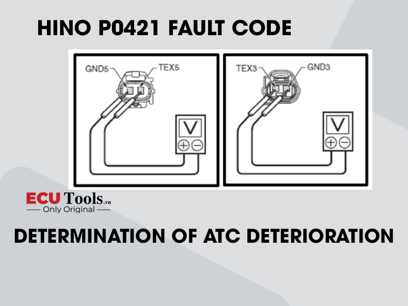
- Use the electrical tester to measure the resistance between the terminals of the exhaust gas temperature sensor 1 (ATC upstream) and the exhaust gas temperature sensor 2 (ATC downstream).
| MEASUREMENT CONDITIONS | TESTER CONNECTIONS | STANDARD VALUES |
| Starter switch: LOCK | Exhaust gas temperature sensor 1 (ATC upstream): TEX5 – GND5
Exhaust gas temperature sensor 2 (ATC downstream): TEX3 – GND3 |
|

Do the measurements meet the standard value?
| Yes | Go to Step 8 |
| No | Replace the exhaust gas temperature sensor 1 (ATC upstream) and the exhaust gas temperature sensor 2 (ATC downstream). Go to Step 8. |
Step 8: Inspect the sensor power supply
- Set the starter switch to the “ON” position
- Use the electrical tester to measure the voltage between the terminals of the exhaust gas temperature sensor 1 (ATC upstream) and the exhaust gas temperature sensor 2 (ATC downstream) vehicle-side connector.
| MEASUREMENT CONDITIONS | TESTER CONNECTIONS | STANDARD VALUES |
| Starter switch: ON |
TEX5 – GND5
TEX3 – GND3 |
4.5 – 5.5 V |

Do the measurements meet the standard value?
| Yes | Go to Step 11. If any failure was found at steps 5 – 7, clear all past DTCs. Check that no DTC is detected after test drive. |
| No | Go to step 9 |
Step 9: Inspect for short-circuit of the exhaust gas temperature sensor 1 (ATC upstream) and the exhaust gas temperature sensor 2 (ATC downstream) harness.
- Set the starter switch to the “LOCK” position
- Connect the signal check harness to the engine ECU. (Do not connect harness to the ECU)
- Use the electrical tester to measure the resistance between the terminals of the engine ECU and ground
| MEASUREMENT CONDITIONS | TESTER CONNECTIONS | STANDARD VALUES |
| Starter switch: LOCK | Engine ECU (signal check harness):
|
∞ Ω |

Do the measurements meet the standard value?
| Yes | Go to Step 10 |
| No | Repair or replace the harness. Go to Step 10 |
Step 10: Inspect disconnection of the exhaust gas temperature sensor 1 (ATC upstream) and the exhaust gas temperature sensor 2 (ATC downstream) harness
- Connect the exhaust gas temperature sensor 1 (ATC upstream) and the exhaust gas temperature sensor 2 (ATC downstream) connector.
- Use the electrical tester to measure the resistance between the terminals of the engine ECU (signal check harness)
| MEASUREMENT CONDITIONS | TESTER CONNECTIONS | STANDARD VALUES |
| Starter switch: LOCK | Engine ECU (signal checkharness):
|
|
Do the measurements meet the standard value?
| Yes | Go to Step 11. If any failure was found at the Steps 5 – 9, clear all past DTCs. Check that no DTC is detected after test drive. |
| No | Repair or replace the harness. Clear all past DTCs. Check that no DTC is detected after test drive. |
Step 11: Inspect the exhaust gas temperature sensor 3 (DOC inlet) connector.
Check the connection of the exhaust gas temperature sensor 3 (DOC inlet) connector (looseness and poor contact)
Were any failures found?
| Yes | Connect securely, repair if needed. Go to Step 12. |
| No | Go to Step 12. |
Step 12: Inspect the exhaust gas temperature sensor 3 (DOC inlet)
- Check the installation of the exhaust gas temperature sensor 3 (DOC inlet)
- Make sure there is no dirt, damage or clogging in the sensing unit of the exhaust gas temperature sensor 3 (DOC inlet)
Were any failures found?
| Yes | Clean the sensing unit and install it properly. If damaged, replace the exhaust gas temperature sensor 3 (DOC inlet). Go to Step 13 |
| No | Go to Step 13 |
Step 13: Inspect the exhaust gas temperature sensor 3 (DOC inlet) unit
- Set the starter switch to the “LOCK” position
- Disconnect the exhaust gas temperature sensor 3 (DOC inlet) connector
- Use the electrical tester to measure the resistance between the terminals of the exhaust gas temperature sensor 3 (DOC inlet)
| MEASUREMENT CONDITIONS | TESTER CONNECTIONS | STANDARD VALUES |
| Starter switch: LOCK | Exhaust gas temperature sensor 3 (DOC inlet):
|
|

Do the measurements meet the standard value?
| Yes | Go to Step 14. |
| No | Replace the exhaust gas temperature sensor 3 (DOC inlet). Go to Step 14. |
Step 14: Inspect the sensor power supply
- Set the starter switch to the “ON” position
- Use the electrical tester to measure the voltage between the terminals of the exhaust gas temperature sensor 3 (DOC inlet) vehicle-side connector.
| MEASUREMENT CONDITIONS | TESTER CONNECTIONS | STANDARD VALUES |
| Starter switch: LOCK | Engine ECU (signal check harness):
|
∞ Ω |
| Yes | Go to Step 17. If any failure was found at the step 11 – 13, clear all past DTCs. Check that no DTC is detected after test drive. |
| No | Go to Step 15. |

Step 15: Inspect for short-circuit of the exhaust gas temperature sensor 3 (DOC inlet) harness.
- Set the starter switch to the “LOCK” position
- Connect the signal check harness to the engine ECU. (Do not connect harness to the ECU)
- Use the electrical tester to measure the resistance between the terminals of the engine ECU and ground.
| MEASUREMENT CONDITIONS | TESTER CONNECTIONS | STANDARD VALUES |
| Starter switch: LOCK | Engine ECU (signal check harness):
|
∞ Ω |

Do the measurements meet the standard value?
| Yes | Go to Step 17. If any failure was found at the step 11 – 15, Clear all past DTCs. Check that no DTC is detected after test drive. |
| No | Repair or replace the harness. Clear all past DTCs. Check that no DTC is detected after test drive. |
Step 16: Inspect disconnection of the exhaust gas temperature sensor 3 (DOC inlet) harness
- Connect the exhaust gas temperature sensor 3 (DOC inlet) connector
- Use the electrical tester to measure the resistance between the terminals of the engine ECU (signal check harness)
| MEASUREMENT CONDITIONS | TESTER CONNECTIONS | STANDARD VALUES |
| Starter switch: LOCK | Engine ECU (signal check harness):
|
|
| Yes | Replace the ATC |
| No | Procedure completed. (Temporary loose connection) |
Step 17: Test drive
- Set the starter switch to the “ON” position
- Change the [DPR soot amount] using the diagnostic tool
- Set the starter switch to the “LOCK” position
- Monitor the [DPR mode] set
- Start the test drive
- Once the [DPR mode] reads any of “6, 7, 15, 23, 24, 27 or 28”, bring vehicle speed to “0” and keep idling for 60 seconds
| MEASUREMENT CONDITIONS | STANDARD VALUES |
| Starter During the DPR automatic regeneration: LOCK | Vehicle interdiction → Vehicle start |
Was DTC P0420 recorded on the combination meter?
| Yes | Replace the ATC |
| No | Procedure completed. (Temporary loose connection) |
Whatsapp: +84.899.402.402
Facebook: ECUTools.vn
Youtube: ECUToolsvn
Tiktok: ECUTools
Website: ECUTools.vn
RELATED NEWS
See all